
Foshan Fulan Laser Technology Co., Ltd.
National Hotline: 0757-29899345
Manager Wen: 18902563402
Fax: 0757-29899345
Business QQ: 2801827697
E-mail: china@fsfulan.com
Address: No.14, Leliu Port Intensive Industrial Zone, Shunde District, Foshan CityThe high-tech zone almond altar town, shunde, foshan city shun industry west road no. 15 cimc valley 20 9 / f, building B
In EzCad2, each file has 256 pens, with pen numbers ranging from 0 to 255. The concept of "pen" is equivalent to a set of set processing parameters. The parameter setting can choose the default value, or change it as required.
 Indicates that the current pen needs to be processed, double-click this icon to change it.
 It means that the current pen is not processed, double-click this icon to change it.
Color: indicates the color of the current pen, double-click the color bar to change the color.
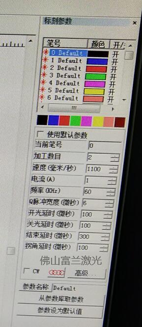
Current pen number: which group of processing parameters is currently in use. In EzCad, the concept of "pen" is equivalent to a set of set processing parameters.
Number of processing: indicates the number of processing times that all objects correspond to the current parameters.
Speed: indicates the marking speed of the current processing parameters
Current (A): Indicates the laser current used by the current processing parameters.
Frequency: indicates the frequency of the laser for the current processing parameters.
Q pulse width: If it is in YAG mode, the high level time of the Q pulse of the Q pulse width laser.
Turn-on delay: the delay time of laser turn-on at the beginning of marking. Setting the appropriate light-on delay parameter can remove the "match head" that appears at the beginning of marking, but if the light-on delay parameter is set too large, it will cause the phenomenon of missing pens in the initial section. It can be a negative value, which means that the laser emits light in advance.
Light-off delay: the delay time of laser turning off at the end of marking. Setting appropriate light-off delay parameters can eliminate the non-closing phenomenon that occurs when the marking is completed, but if the light-off delay is set too large, it will cause a "match head" in the end section. Cannot be negative.
End delay: Under normal circumstances, it takes a period of response time from when the light-off command is issued to when the laser is completely turned off. Setting a proper end delay is to give the laser sufficient light-off response time so that the laser can be completely turned off. The purpose of the next marking is to prevent light leakage and spot fluttering.
Corner delay: the delay time between each segment during marking. Setting appropriate corner delay parameters can eliminate the rounding phenomenon that occurs when marking right angles, but if the corner delay is set too large, the marking time will increase, and there will be key phenomena at the corners.
After pressing the advanced button, the system will pop up the advanced parameter dialog box as shown in the figure below.
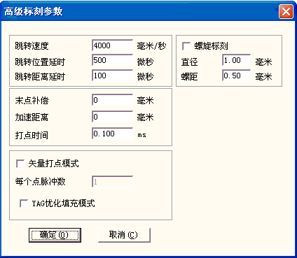
Jump speed: Set the jump speed corresponding to the current parameter.
Jump delay: Set the marking jump delay.
Position delay: Jump position delay.
Distance delay: Jump distance delay.
After each jump movement is completed, the system will automatically wait for a period of time before continuing to execute the next command.
End point compensation: Generally, this parameter does not need to be set. This value can only be set when the end point can not be reached by adjusting the delay parameter during high-speed processing. It is mandatory to continue marking a straight line with the length of the end point compensation distance at the end of processing. . Negative values are acceptable.
Acceleration distance: Properly set this parameter to eliminate uneven dots at the beginning of the marking.
Dotting time: when there are some objects in the object, the time for each point to emit light.
Spiral marking: Valid when checked. It is mainly used when the line needs to be thickened when marking a single line, which can save time and improve efficiency.
Diameter: The diameter of the spiral circle during spiral marking, that is, the width of the line marked with spiral mode.
Pitch: The distance between the centers of two adjacent circles during spiral marking. Set an appropriate value according to the size of the point that the laser acts on the surface of the object. If the pitch is set too large, the marked line will have shading, and if it is set too small, it will increase the marking time.
Vector Dot Mode: It is mandatory to define the fixed number of pulses when the laser processes each point.
YAG optimized filling mode: Use YAG laser marking machine to optimize the filling and marking of highly reflective materials.
Note: The function of this function is to solve the problem of irregular lines in the filling and marking of the high-brightness metal material surface by the YAG laser, so as to obtain a good filling effect. When using this function, the PWM signal of the control card must be used as the pulse modulation signal of the Q drive and connected to the Q drive to obtain the corresponding effect.
Quality assurance, full service!
Let the value of equipment exceed customer expectations!
Manager Wen: 18902563402

Scan Mobile Version |